Ultra-Wide, No-Distortion Optics <BR>for Drone and UAS Gimbal ISR Payloads
<p style="padding-left: 0px; padding-right: 0px;">Reliable wide-area electro-optical imaging aboard a drone or Unmanned Aerial Systems (UAS) gimbal often depends on maintaining a straight, geometrically consistent image across a wide field of view [1]. This application note examines how ultra-wide, no-distortion lenses can be used for gimbals integrated on the lighter and smaller end of drone/ UAS used in Intelligence, Surveillance and Reconnaissance (ISR) missions, where a single lens built for wide-area situational awareness, collision avoidance, and search coverage can replace multiple narrower-FOV lenses. </P>
❮
❯
Theia telephoto lenses provide long-range imaging for ANPR, traffic monitoring, and Intelligent Transportation Systems.
<p style="padding-left: 0px; padding-right: 0px;">A conventional wide-angle or fisheye lens compresses and curves straight lines near the frame edge, degrading automated target detection, distance estimation, and any downstream processing that assumes a consistent projection. A rectilinear, no-distortion lens preserves straight-line geometry across the full field of view with improved edge resolution, increasing the probability of target detection in the image periphery. Theia Technologies' family of ultra-wide, no-distortion lenses featuring patented <a href="https://www.theiatech.com/support/white-papers-case-studies-editorials/english/eliminate-distortion-in-wide-angle-imaging/">Linear Optical Technology®</a> provide these performance characteristics and serve as an example throughout this note.</P>
<p style="padding-left: 0px; padding-right: 0px;">A gimbal payload's optics are constrained top-down and bottom-up. Top-down, the drone or UAS platform's SWaP class fixes the size, weight, and power budget available before any specific lens is chosen. Bottom-up, the mission itself sets the performance the optics must deliver regardless of that budget. This note is organized around that same framework: Part A addresses the top-down constraints, the SWaP budget that a program's airframe and acquisition documents impose on the gimbal payload, including optics hardware — and Part B addresses the bottom-up mission performance requirements for ISR situational awareness, collision avoidance, and search coverage and how Theia’s family of ultra-wide, no-distortion lenses fulfill these performance requirements. <br></p>
<span style="font-size: 10px;"><strong>[1]</strong> J. R. Wilson, “EO/IR sensors boost situational awareness,” Military Aerospace, Jan. 19, 2016, https://www.militaryaerospace.com/communications/article/16709096/eo-ir-sensors-boost-situational-awareness">https://www.militaryaerospace.com/communications/article/16709096/eo-ir-sensors-boost-situational-awareness<br></span>
Part A: Top-Down SWaP Constraints (Size, Weight, Power)
1. How Is Gimbal Payload Weight Specified?
2. How Is Gimbal Payload Power Specified?
1. How Is Gimbal Payload Weight Specified?
2. How Is Gimbal Payload Power Specified?
1. How Is Gimbal Payload Weight Specified?
Drone and UAS aircraft can be categorized using the U. S. Department of Defense (DoD) official UAS Group classification, which categorizes the aircraft itself (not the gimbal payload), by Maximum Gross Take-Off Weight (MGTOW), normal operating altitude, and speed [2].
| Group |
MGTOW |
Normal operating altitude | Speed |
|---|---|---|---|
| Group 1 | 0–20 lb (~9 kg) | < 1,200 ft AGL | < 100 kt |
| Group 2 | 21–55 lb (~25 kg) | < 3,500 ft AGL | < 250 kt |
| Group 3 | < 1,320 lb (~600 kg) | < 18,000 ft MSL | < 250 kt |
| Group 4 | > 1,320 lb | < 18,000 ft MSL | Any airspeed |
| Group 5 | > 1,320 lb | > 18,000 ft MSL | Any airspeed |
No DoD or industry standard subdivides the gimbal payload itself into weight classes, and gimbal-manufacturer documentation uses only informal adjectives (“micro,” “mini,” “compact,” “low-SWaP”) with no consistent thresholds from one manufacturer to the next [3]. In practice, gimbal payload weight and power are specified the way most avionics subsystems are — top-down and bottom-up. Top-down, the airframe’s MGTOW ceiling and any minimum payload-capacity requirement set in program acquisition documents (ICDs, CDDs, RFPs) fix the total weight and power budget available for the imaging system payload; that budget is allocated case-by-case per platform and mission [4].
While nothing excludes the use of ultra-wide, no-distortion rectilinear lenses on heavier airframes, these lenses are well suited for close-in situational awareness, collision avoidance, and wide-area search requirements— a mission profile for small, low-altitude airframes like those at the smallest end of Group 1. Nothing about Theia’s ultra-wide, no distortion lens family’s size, weight, or power draw would exclude it from heavier airframes; if anything, the budget argument above Group 1 only gets easier to satisfy as MGTOW increases. With that said, Group 3–5 platforms typically fly higher and need longer-standoff identification range, a narrow-FOV and longer-focal-length optics, an imaging task this lens family does not fulfill (Theia offers motorized zoom and telephoto lenses for those situations) [5].
The DoD UAS Group classification scales with group size [6]. Group 1 and 2 platforms — the segment Theia's ultra-wide, no distortion lens line targets, typically carry the simplest sensor package: a single EO camera, or a basic EO/thermal dual-sensor payload with a short-range onboard NIR illuminator for night use. Moving up to Group 3, gimbals commonly add a laser rangefinder alongside the EO/IR channels to support longer-standoff detection and identification [6]. Group 4 and 5 platforms carry the most complete sensor suites, adding laser rangefinders and additional thermal or multi-spectral channels to the EO/IR payload.
Theia’s ultra-wide, no distortion lens line spans 50–99 grams body weight across its five configurations. That lens weight is one part of the total payload weight budget alongside the image sensor, the gimbal’s stabilization mechanism, the housing, illuminator and onboard electronics and cabling; how large a share the lens represents depends entirely on the specific program’s own top-down weight allocation, not on any fixed lens-to-payload ratio.
| MY125 / SY125 | MY110 / SY110 | ML183 / SL183 | MY23F | |
|---|---|---|---|---|
| Model Variation | Fixed Focal Length | Fixed Focal Length | Varifocal | Fixed Focal Length |
| Lens Length to Mount | 58.9mm | 56mm | 44.3mm | 44mm |
| Total Track Length (TTL) | 71mm | 68mm | 62mm | 62mm |
| Diameter | Ø47.00mm - Ø48.00mm* | Ø36.35mm - Ø49.00mm* | Ø50.00mm | Ø36.50mm |
| Weight | 83 - 117g | 47 - 51g | 58 - 66g | 62g |
[3] USSOCOM Modular Payload (MP) Design Standard, developed with the Johns Hopkins University Applied Physics Laboratory, https://www.jhuapl.edu/work/publications/mod-payload; full standard available via the Defense Technical Information Center, https://apps.dtic.mil/sti/pdfs/AD1167779.pdf.
[4] “What is SWaP-C?,” BAE Systems, https://www.baesystems.com/en-us/definition/what-is-swap-c.
[5] U.S. Naval Air Systems Command (NAVAIR), Request for Information: Medium Range Tactical (MRT) Unmanned Aircraft System (UAS), PMA-263, https://govtribe.com/opportunity/federal-contract-opportunity/request-for-information-rfi-for-medium-range-tactical-mrt-unmanned-aircraft-system-uas-pma-263-24326024; see also “Marine Corps looking into new medium-range tactical drone as it pushes small UAS capabilities,” DefenseScoop, Feb. 17, 2026, https://defensescoop.com/2026/02/17/marine-corps-medium-range-tactical-drone-suas/.
[6] “UAV Groups and Classes,” Times Microwave Systems, https://timesmicrowave.com/uav-groups-classes/; see also WESCAM MX-Series, L3Harris, https://www.l3harris.com/all-capabilities/wescam-mx-series.
2. How Is Gimbal Payload Power Specified?
Most of a gimbal ISR payload’s electrical budget is spent well outside the lens. The gimbal’s brushless stabilization motors and control electronics — which fuse gyroscope and accelerometer data to hold the line of sight steady and pass video to the downlink transmitter — draw continuously throughout flight [7]. The image sensors and any onboard video processing or AI-assisted detection running on the payload add a further continuous load, and that load rises sharply if the payload carries a cooled thermal imager: the cryocooler a cooled detector requires draws more power than an uncooled microbolometer core and is itself a maintenance item [8]. Illuminators and, where equipped, a laser rangefinder — both present on fielded EO/IR gimbal payloads — add further load of their own [9].
Theia's rectilinear lens family is fixed-focus or varifocal. It has no motorized zoom, focus, or iris mechanism. Because of this, the lens itself adds effectively zero electrical draw to the payload's power budget. This is different from motorized zoom lenses, whose actuators for zoom, focus, and iris control add a continuous or intermittent power load of their own [10].
This ultra-wide, no-distortion lens design offers two further power advantages.
First, the lens corrects distortion optically, not through software. Because of this, the payload's processor never has to run a dewarping algorithm on the video stream — a processing step an equivalent fisheye-plus-software approach would need to run on every frame.
Second, some programs may select the DC auto-iris version of the lens. A DC-drive iris is controlled directly by circuitry inside the camera rather than by a dedicated amplifier built into the lens [11], so it does not add a separate motor-drive circuit to the lens itself. Because of this, its contribution to the payload's power budget stays minimal.
Power consumption in a gimbal payload built around Theia's ultra-wide, no-distortion lenses is therefore driven almost entirely by the sensor, illuminator, and stabilization electronics — not by the optic itself.
[8] “What is Cooled vs Uncooled Thermal Imaging? Beginner Guide,” Counter UAV Radar, https://www.counteruavradar.com/en/knowledge-base/what-is-cooled-vs-uncooled-thermal-imaging/.
[9] DJI Enterprise, Zenmuse H30 Series product specification, https://enterprise.dji.com/zenmuse-h30-series.
[10] Graflex Inc., “Motorized Zoom Lens General Data,” https://graflex.com/products/motorized-zoom-lenses/general-data.
[11] “How to Distinguish Auto Iris, Manual Iris and P-Iris,” AICO Lens, https://aico-lens.com/resource/how-to-distinguish-auto-iris%EF%BC%8Cmanual-iris-and-p-iris/.
Part B — Bottom-Up Mission Performance Requirements for ISR.
1. Why Does Optical Distortion Matter for an Ultra-Wide Imaging System?
1. Why Does Optical Distortion Matter for an Ultra-Wide Imaging System?
In this section we address the bottom-up mission performance requirements for ISR — situational awareness, collision avoidance, and search coverage -- that the optical design itself must satisfy: field of view and optical distortion at the frame edge, resolution performance, wavelength coverage and Near-IR correction, and shock and vibration durability.
1. Why Does Optical Distortion Matter for Ultra-Wide Imaging in ISR Missions?
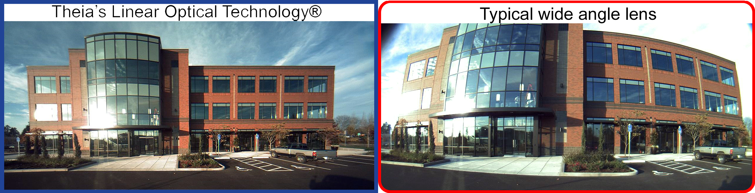
A conventional wide-angle or fisheye lens covers a wide field of view by compressing and curving straight lines as they approach the frame edge, the familiar “bowed” look where vertical building edges bend inward [12]. That distortion is a functional problem in a gimbal ISR imaging system: an operator judging distance or bearing at the edge of the frame, or an automated detection algorithm gets a geometrically unreliable answer exactly where a wide lens is doing the most work (Fig. 1) [13]. There are three main solutions to wide angle coverage that are detailed below: "Figure 1. (Left) Linear Optical Technology® preserves straight building lines across the full frame; (Right) a typical wide-angle lens shows the characteristic barrel-style distortion toward the edges. Example captured with a Theia ultra-wide lens."
Fisheye Lenses with Software De-warping
The conventional fix is downstream rather than optical: capture through a fisheye lens, which can reach FOVs of roughly 180° or more [14], then de-warp the image in software before it reaches a human viewer or a detection algorithm. This comes at the cost of power for de-warping, which can reduce the AI identification algorithm’s power budget, introduce latency, and prevent real-time imaging.
Multiple Cameras & Lenses Instead of One Wide Lens
Another approach sidesteps the single-lens FOV ceiling altogether: multiple narrower-FOV cameras electronically stitched into one combined image. Documented trade-offs in general security-camera literature run the other direction from a single wide lens — higher pixel density across the combined field, suited to identification rather than only detection, at the cost of added size, weight, power, and cost from multiple sensors, plus stitching-seam and parallax artifacts at close range [15].
Rectilinear Lenses with Optical Distortion Correction
A rectilinear, no-distortion optical design corrects the frame-edge distortion problem at the optical level within its effective FOV range (up to ~135°), holding straight lines straight with minimal residual distortion and without a downstream software-dewarping step. Theia Technologies’ lenses with patented Linear Optical Technology® accomplish this; the difference is immediately visible when compared to an image of the same subject shot with a typical wide-angle lens (as with Fig. 1).
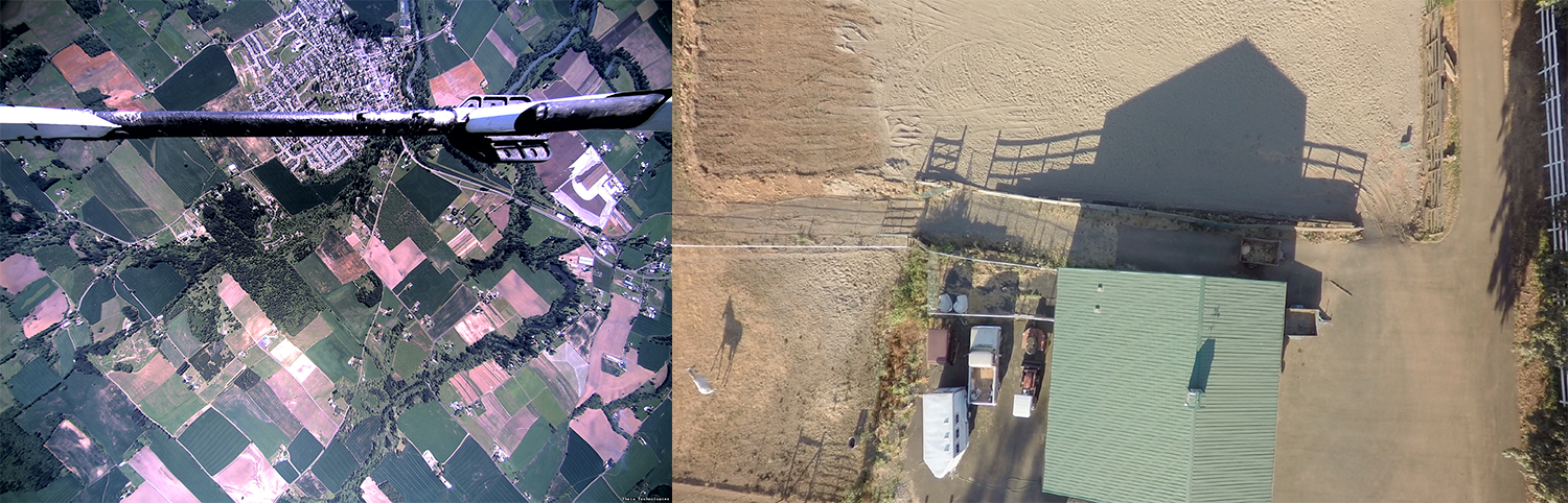
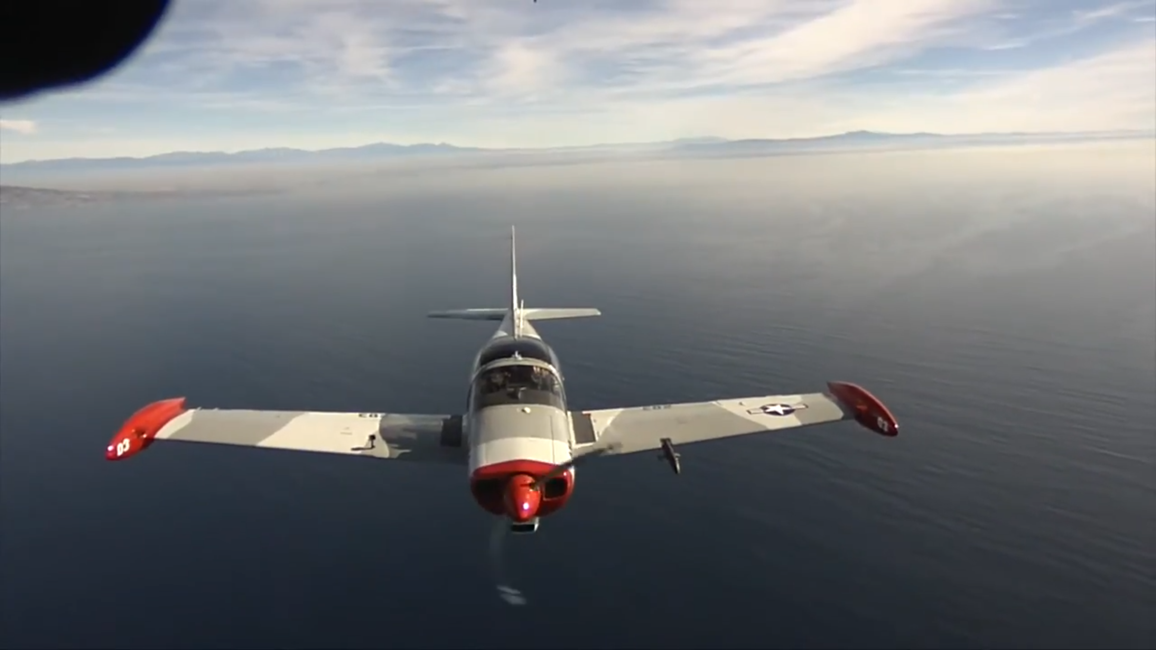
The same correction holds up in an airborne, ultra-wide capture: field boundaries and the aircraft structure in frame stay geometrically straight from center to edge rather than curving toward the corners. Figure 2. (Left) Aerial capture using a Theia ultra-wide lens at approximately 4,000 ft. (Right) Aerial capture using a Theia ultra-wide lens at approximately 45 ft.
Rectilinear bounds: 3D Stretching and Limits of FOV
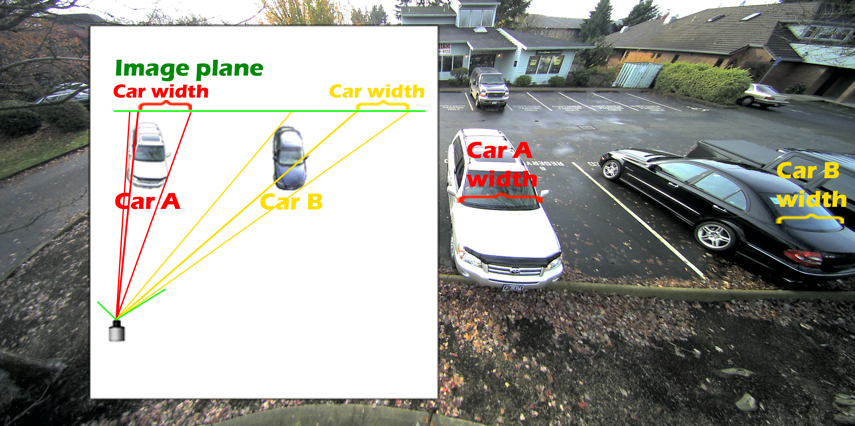
Optical distortion correction, rather than using software, avoids that downstream dewarping step, but not the underlying physics: a rectilinear (“no distortion”) projection maps image position as the tangent of the angle from center, which grows without bound as that angle approaches 90°, making a rectilinear design impractical much past roughly 135° of FOV [13, 14, 16]. Fisheye and other non-rectilinear projections avoid that tangent relationship and so are not bound by the same ceiling. Figure 3. 3D stretching. The objects are projected onto the image plane along the tangent line causing objects at the image edge with dimensions parallel to the lens axis to appear stretched.
This optical correction is not uniform across the full example line. At 135° FOV, the widest configuration in this line (MY125M / MY125M-E) exhibits measurable geometric stretching at the extreme image edges, consistent with operating close to the general practical ceiling for optically-corrected wide-angle designs described above (Fig. 3); the narrower configurations in this line (ranging from 90°–120°) do not show this effect.
[13] “Surround-View Fisheye Optics in Computer Vision and Simulation,” arXiv:2402.12041, https://arxiv.org/html/2402.12041v2.
[14] “Fisheye Imaging Lenses,” Edmund Optics, https://www.edmundoptics.com/f/fisheye-imaging-lenses/13516/.
[15] Axis Communications, “Panoramic Cameras” white paper, https://whitepapers.axis.com/en-us/panoramic-cameras.
[16] “Optics Primer: Rectilinear Projection Lenses,” PhotonsToPhotos, https://www.photonstophotos.net/GeneralTopics/Lenses/Optics_Primer/Optics_Primer_24.htm.
2. Matching Resolution to Sensor Pixel Pitch
Matching a specific lens model's supported resolution to the sensor mounted on a given gimbal ensures the lens is not the limiting factor in terms of resolution performance of the imaging system. "High resolution" is only meaningful relative to a sensor's pixel pitch: Sony's Pregius and Pregius S global-shutter CMOS sensor families — the sensor chips most commonly integrated into gimbal EO daylight channels — span pixel pitches from 3.45 µm (2nd-generation Pregius, e.g. IMX252, IMX265) down to 2.74 µm (Pregius S, e.g. IMX547), all within the 1/1.8" optical format this lens line's largest configuration is designed to cover [17]. The lens selected should maintain at least 20% Modulation Transfer Function (MTF) at the sensor's Nyquist frequency for the sensor's pixel [18].
Further, as previously mentioned, ultra-wide, no-distortion lens designs increase resolving power at the edge of the image compared to conventional lenses with barrel distortion which can increase the usable area of detection in ISR missions. Conventional wide-angle lenses with fisheye or barrel distortion compress the information at the image edge, causing loss of resolution which cannot be recovered during software correction.
Most Theia models were designed for a 2.3 micron size pixel and measured to 200 lp/mm resolution consistent with 5 MP-class sensors, while one model is designed for larger pixels of 3 MP-class sensors.
| MY125 / SY125 | MY110 / SY110 | ML183 / SL183 | MY23F | |
|---|---|---|---|---|
| Model Variation | Fixed Focal Length | Fixed Focal Length | Varifocal | Fixed Focal Length |
| Largest Sensor Format | 1/2.5" | 1/2.5" | 1/2.3" | 1/1.8" |
| Resolution | 5+mpx | 3+mpx | 5+mpx | 5+mpx |
| Resolving Power | 200 lp/mm | 160 lp/mm | 200 lp/mm | 200 lp/mm |
Mission Temperature Variations and Athermalization
ISR missions carry a gimbal payload across a wide span of climates and altitudes over its service life — from sustained desert heat to high-altitude and arctic cold. If the range of operating conditions is the underlying problem; athermalization is the optical answer to it.
Resolution is temperature-sensitive: a lens that drifts off its focal plane loses the MTF it was rated for at the sensor’s Nyquist frequency, discussed above [20]. That matters for ISR, where temperature-driven image degradation from loss of focus can compromise the mission. Athermalization compensates for temperature-driven refractive-index change with a passive optical/mechanical design rather than an active-refocus mechanism [21].
Within Theia’s lens line, focus is held from -20°C to 60°C without a mechanical refocus step — an 80°C span — and that same athermalized design holds the lens on its focal plane, the failure mode that matters most for a fixed-focus optic sealed in a gimbal ball with no in-flight refocus capability.
This operating range spans, to a wide extent, the ambient conditions of the MIL-STD-810 - the U.S. Department of Defense's environmental engineering standard for proving that equipment can survive the shock, vibration, temperature, and other stresses it will face over its service life.
MIL-STD-810 divides these thermal operating environments into named climatic categories, each keyed to a specific ambient temperature range — Basic Hot (A2, 30 to 43°C) and Hot Dry (A1, 32 to 49°C) on the high-temperature side, and Mild Cold (C0, -19 to -6°C), Basic Cold (C1, −21 to −32°C), Cold (C2, −37 to −46°C), and Severe Cold (C3, −51°C) on the low-temperature side [22].
When hardware is unable to meet these ranges, mitigation may typically be applied at the platform level rather than in the lens itself. Small EO/IR gimbal payloads overwhelmingly favor passive, uncooled sensor and optical designs [23], and where added thermal margin is needed for a sensitive sensor, passive heat-sinking into the gimbal housing is the more common practice rather than an active cooler or fan, since active cooling adds size, weight, and power (SWaP) cost that a visible/near-IR sensor does not strictly require [24].
In cold conditions where Theia’s lenses are less tolerant, heaters are more common on these payloads, but they are generally sized to protect the optical window against fogging and icing and to protect cold-sensitive mechanical and power subsystems — rather than to actively condition the full lens barrel — and manufacturer cold-weather guidance emphasizes pre-flight warm-up and reliance on the payload's own operating self-heat over a continuously-running dedicated optics heater [25].
[9] DJI Enterprise, Zenmuse H30 Series product specification, https://enterprise.dji.com/zenmuse-h30-series.[17] Basler, “Comparing Sony’s IMX CMOS Sensor Series,” baslerweb.com/en-us/learning/cmos-sensor-selection/; FRAMOS, “Sony Pregius IMX253 Polarization Image Sensor,” framos.com/products/sensors/area-sensors/imx253mzr-c-22485/; FRAMOS, “Sony Pregius IMX535 – 12.42 MP Monochrome CMOS Sensor,” framos.com/products/sensors/area-sensors/imx535aamj-c-24259/.
[18] “The Modulation Transfer Function (MTF) and MTF Curves,” Edmund Optics, https://www.edmundoptics.com/knowledge-center/application-notes/imaging/modulation-transfer-function-mtf-and-mtf-curves/; ISO 12233:2017/2024, Photography — Electronic still picture imaging — Resolution and spatial frequency responses, https://www.iso.org/standard/71696.html.
[19] “Climate Testing on Drones and UAVs: A Complete Guide,” FDM Makers, https://fdm-makers.com/en/uav-drone-climate-tests-standards-procedures-climate-chamber/.
[20] “Resolution,” Edmund Optics, https://www.edmundoptics.com/knowledge-center/application-notes/imaging/resolution/; C. E. Shannon, “Communication in the Presence of Noise,” Proceedings of the IRE 37(1), 10–21 (1949).
[21] “Athermalization & Ruggedization,” Edmund Optics, https://www.edmundoptics.com/knowledge-center/trending-in-optics/athermalization-ruggedization/.
3. Mapping Field of View and Focal Length to Mission Role
Across ISR, situational-awareness, and collision-avoidance mission sets, the underlying requirement is consistent: cover a wide field of view in a single frame, keep that view geometrically accurate at the edges, and stay inside a size, weight, and power (SWaP) budget the airframe can carry. The table below generalizes that requirement, benchmarks it against documented systems and standards, and shows how Theia's ultra-wide, no-distortion lens line satisfies it.
Table 1. Typical mission requirement vs. Theia's lens line
| Typical mission requirement | Documented benchmark | Theia's lens line | How Theia solves it |
|---|---|---|---|
| Wide-area, single-frame coverage — replace multiple narrow-FOV cameras with one view | Conventional systems typically need multiple stitched sensors to achieve comparable wide-area coverage, at the cost of added complexity and integration overhead | 90°–135° FOV from a single lens, single sensor | Matches or exceeds the multi-sensor benchmark in one optical channel — no stitching seams, no inter-sensor sync, no added sensor hardware |
| Safety-critical situational awareness / detect-and-avoid coverage | FAA-sponsored research recommends a 180° minimum FOV, up to 360° for full coverage of overtaking traffic [12] | Widest configuration (MY125M/-E): 135° FOV | Delivers roughly three-quarters of the full safety-driven FOV target, without distortion from a single lens; multiple units can be paired toward full 360° coverage at a fraction of the sensor count and weight of conventional arrays |
| Usable geometry at the edge of a wide frame — not just wide, but accurate | Conventional wide-angle/fisheye optics bow straight lines at these angles, degrading both human interpretation and automated detection/tracking | Rectilinear, no-distortion design: < 1–3% residual barrel distortion across the full 90°–135° range | Preserves straight-line geometry edge-to-edge with no compression and no lost resolution, so the wide FOV is usable for search, tracking, and targeting — not just wide on paper |
| Fit within a Group 1/2 UAS size, weight, and power (SWaP) budget | Multi-sensor stitching solutions add weight, wiring, and processing that small airframes can't spare One lens, one sensor, one image — no stitching hardware or added processing. | One lens, one sensor, one image — no stitching hardware or added processing | Meets the wide-FOV mission need inside the SWaP envelope of a Group 1/2 UAS gimbal payload |
This wide-FOV positioning, spanning 90–135° across these focal lengths, generally corresponds to wide-area search roles, where a single optical channel is meant to replace multiple narrower-FOV cameras, provided the image stays usable at the edges, both in terms of geometrical representation and resolution performance. Figure 4. Reference imagery illustrating the wide-FOV, full-airframe imaging problem in aircraft-mounted cameras — the same undistorted, edge-to-edge geometry that gimbal-mounted collision-avoidance and situational-awareness applications can employ with ultra-wide, no-distortion optics.
4. Wavelength Requirements and Near IR Correction
An EO/IR dual-sensor gimbal payload must satisfy two separate wavelength requirements at once, each falling to a different sensor. The electro-optical (EO) channel covers the visible band and extends into the near-infrared, typically spanning roughly 400–900 nm [29] — closely matching the 435–940 nm band Theia’s lens line is corrected across, discussed below. The IR channel, by contrast, is a separate thermal-imaging path operating in long-wave infrared (LWIR), 8–14 micron [30]. A mid-wave infrared (MWIR, 3–5 micron) channel is available as a higher-performance alternative to LWIR, but MWIR detectors typically require cryogenic cooling. The two subsections below cover the pieces of this wavelength budget that bear directly on lens selection: the optical correction a lens needs to hold focus across both the visible and NIR portions of the EO channel, and the practical reach of onboard NIR illumination at night.
Why Does NIR Correction Matter?
A lens designed only for visible wavelengths experiences focus shift when switching to NIR, because different wavelengths focus at different optical positions. A properly wavelength-corrected lens holds focus without a mechanical refocus step when a gimbal camera switches between color-day and monochrome-IR-night modes, useful for a lens sealed inside a gimbal ball with no in-flight manual-adjustment capability. In ISR missions, this can enable a single visible/NIR-corrected lens to support Day/Night EO/IR imaging, rather than requiring separate optics for daytime visible imaging and nighttime NIR imaging.
What Is the Practical Range of Onboard Illumination?
Onboard drone illuminators are a close/medium-range tool, not a substitute for passive thermal imaging at longer standoff: illumination intensity falls off with the inverse square of distance [32], so longer-range detection is handled by passive thermal (LWIR, 8–14 micron) imaging rather than active illumination [30].
| Wavelength |
Characteristics |
Typical use |
|---|---|---|
| 850 nm |
~2x sensor response vs. 940 nm; longer effective range and brighter image; faint visible red glow at the source No |
General-purpose night imaging, longer standoff, non-covert operations |
| 940 nm |
Fully invisible to the human eye; ~30–50% shorter effective range at equal power vs. 850 nm No |
Covert surveillance, law enforcement, tactical/military operations |
Ultra-wide lenses for this role are typically corrected across a visible-through-NIR band (435–940nm), though coverage varies by model:
| MY125 / SY125 | MY110 / SY110 | ML183 / SL183 | MY23F | |
|---|---|---|---|---|
| IR Correction |
No | 435 - 940nm (Day/Night) | 435 - 850nm (Day/Night) | 435 - 850nm (Day/Night) |
[30] “Comprehensive Guide to LWIR Imaging Systems,” LightPath Technologies, https://www.lightpath.com/insights/comprehensive-guide-to-lwir-imaging-systems; see also The Infrared & Electro-Optical Systems Handbook, Vol. 8 (SPIE Press, 1993/2023).
[31] “Understanding the IR Spectral Band,” Sierra-Olympia Technology, https://sierraolympia.com/understanding-the-ir-spectral-band/.
[32] “Inverse-Square Law,” Illuminating Engineering Society, https://ies.org/definitions/inverse-square-law/.
5. Environmental Requirements -Shock, Vibration & Temperature
The Requirement
For a lens mounted to an aircraft gimbal, the mission need is simple to state and hard to meet: hold image quality through sustained shock and vibration, with no drift in focus, no element shift, and no mechanical failure.
MIL-STD-810 is the U.S. Department of Defense's environmental engineering standard for proving that equipment can survive the shock, vibration, temperature, and other stresses it will face over its service life.
It isn't a single pass/fail spec. It's a library of test methods — Method 514 for vibration, Method 516 for shock, and Methods 501/502/503 for temperature and thermal shock, among others — that each program tailors to its own platform and mission profile. The reference levels drawn from these methods are commonly cited as baseline expectations for avionics/vetronics equipment [22].
How Theia's Lenses Measure Up
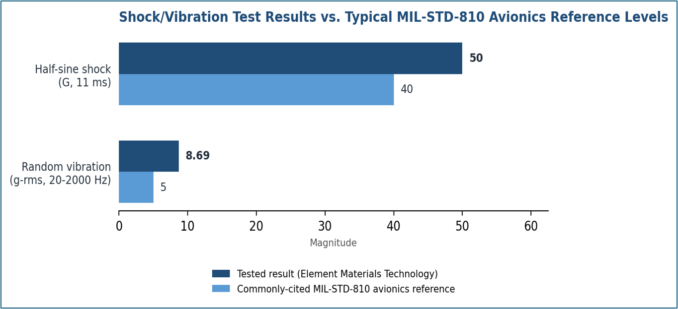
Theia lenses have demonstrated performance above the commonly cited MIL-STD-810 avionics/vetronics reference levels (see Figure 5)..
Testing of Theia’s ultra-wide lenses was run against a customer statement-of-work specification, not a formal MIL-STD-810 certification plan [33]. But both the shock and vibration tests were conducted at magnitudes above the standard's commonly cited functional-shock and general aircraft-equipment vibration reference levels. Remaining fully functional at those magnitudes indicates Theia's lenses surpass the shock/vibration performance typically expected of MIL-STD-810-referenced avionics equipment.
Two Configurations, Further Ruggedized
The MY125M-E and MY23F go beyond the mechanical design shared across the rest of the line:
• MY125M-E — reinforced C-mount housing; focus and iris rings locked with a thumbscrew-and-setscrew mechanism to prevent element and ring shift under shock/vibration. Weight penalty is minimal: 103 g vs. 99 g for the standard MY125M.
• MY23F — elements fixed directly within a metal housing rather than a standard barrel; focus ring locked with three setscrews; C-mount/M12 mount integrated directly into the housing rather than attached as a separate ring, eliminating the mount-separation failure mode that threaded, non-integrated mounts can suffer under impact.
Validated Beyond the Test Bench
The MY23F's construction has also held up outside the formal shock and vibration test program: in Theia's vehicle crash-test case study, it held focus and showed zero failures across more than 45 automotive impact tests. The MY125 has been used in Aeronautics training and NASA drone applications without reported failure.
Bottom line: every configuration in the line has documented shock/vibration test data, two are purpose-built for the harshest environments, and the toughest of those has real-world crash-test evidence to back it up. Figure 5. Theia ultra-wide lenses have been tested to and withstand shock and vibration levels exceeding commonly cited MIL-STD-810 avionics references.
What About Temperature?
MIL-STD-810 addresses thermal stress through Method 501.7 (High Temperature), Method 502.7 (Low Temperature), and Method 503.7 (Temperature Shock), each tailored to a program’s climatic category [22]. As with shock and vibration, formal temperature qualification is performed at the system level by the gimbal or platform integrator. At the lens level, the relevant figure is the operating temperature range for equipment mechanical function and imaging performance. Again, Theia’s ultra-wide, no-distortion lenses operate reliably from -20°C to +60°C.
This range spans the ambient conditions of the - environmental engineering standard for proving that equipment can survive the shock, vibration, temperature, and other stresses it will face over its service life per U.S. Department of Defense's MIL-STD-810 standard for Basic Hot (A2, 30 to 43°C) and Hot Dry (A1, 32 to 49°C) climatic categories, however on the cold side Theia’s lenses only meet the Mild Cold (C0, -19 to -6°C) designation.
Since the environmental qualification is determined at system level, as discussed above, temperatures beyond the lens's own −20°C to +60°C operating range are where platform-level mitigation applies. On the cold side that means the harsher MIL-STD-810 categories introduced above — Basic Cold (C1), Cold (C2), and Severe Cold (C3) beyond the Mild Cold (C0) edge the lens's −20°C floor reaches. Where cold-side mitigation is needed, integrators typically rely on window and battery/mechanical heaters and, less often, passive heat-sinking rather than active cooling — sized and verified against the specific mission's climatic category rather than assumed by default [23] [24] [25]. On the hot side, by contrast, the lens's +60°C ceiling already clears MIL-STD-810's most severe standard category, Hot Dry (A1), so heat rarely requires this kind of mitigation.
Storage temperature — what the lens must survive unpowered and optically idle before and after it flies, whether in a case, a shipping container, a forward staging area, or a vehicle cargo bay — tells a similarly favorable story. Storage ranges for imaging lenses typically run wider than their operating ranges [26], and Theia’s −30°C to +70°C storage range lines up well against MIL-STD-810’s most demanding standard heat category: Hot Dry (A1)’s 33°C to +71°C induced/storage range [22], as well as clearing Mild Cold (C0)’s −21°C to −10°C induced/storage range.
Which Iris Type Fits a Vibration-Optimized Application?
Gimbal payloads accumulate continuous vibration exposure over the operational life of the aircraft, and a lens is judged on mechanical simplicity as well as optical performance [34]. Three iris types are common in ultra-wide gimbal optics:
| Iris Type | Mechanism | Gimbal Consideration |
|---|---|---|
| Fixed | No moving parts; aperture set at manufacturer | Most vibration-tolerant and lightest option; no field adjustment available |
| Manual | User-set aperture ring; no continuous actuation | No continuous actuation wear; aperture is set once at integration and does not move in flight |
| DC Auto iris | Continuous analog drive, constantly adjusting | More moving-part wear over years of vibration exposure, due to continuous actuation; more common on CS-mount, security-oriented designs than C-mount machine-vision integration |
The fixed-iris configuration removes a moving part entirely from a payload where weight and reliability, not variable exposure control, are the binding constraints — the stronger recommendation for small UAS integrations where the mission doesn’t call for field-adjustable exposure.
Manual iris remains the more common configuration where some field-set exposure control is wanted without the continuous-actuation wear of a third type: DC auto-iris.
DC auto-iris lenses remain common elsewhere in the camera market because they continuously compensate for gradual, all-day ambient light changes — a function historically carried by the lens in analog CCTV/security-camera designs, rather than by camera electronics [35].
Day/night mode switching (removing the IR-cut filter to shift from color to monochrome/IR imaging) is a related but separate function; in most modern cameras it's triggered by the sensor's electronic gain crossing a threshold, not by the auto-iris drive signal itself [36].
For a gimbal payload, where exposure control and day/night switching are already handled digitally by the sensor and gimbal electronics, DC auto-iris doesn't solve a problem the platform hasn't already solved elsewhere — which is why manual or fixed iris remains the better fit for a weight- and vibration-optimized gimbal integration.
[22] MIL-STD-810H, Environmental Engineering Considerations and Laboratory Tests, U.S. Department of Defense (Jan. 31, 2019), https://everyspec.com/MIL-STD/MIL-STD-0800-0899/MIL-STD-810H_55998/; see also Method 514.8 (Vibration) and Method 516.8 (Shock) test method overviews, Trenton Systems, https://www.trentonsystems.com/en-us/resource-hub/blog/mil-std-810-vibration-testing-everything-you-need-to-know and https://www.trentonsystems.com/en-us/resource-hub/blog/mil-std-810-shock-testing-overview-method-516.8.
[33] Element Materials Technology (Hillsboro, OR) shock and vibration test reports, conducted against a Theia customer statement-of-work specification: Vibration/Shock Test 1 (2018); Vibration Test 2 (2018, ATB PQVT); Shock Test 3 (2022, Report R17889).
[34] Y. Ge, T. Dunno, J. Singh, et al., “Development of a Drone’s Vibration, Shock, and Atmospheric Profiles,” Applied Sciences 11(11), 5176 (2021), https://www.mdpi.com/2076-3417/11/11/5176.
[35] “Lens Iris Tutorial,” IPVM, https://ipvm.com/reports/lens-iris-tutorial.
[36] Axis Communications, “IR in Surveillance: Day-and-night cameras and Optimized IR,” June 2018, https://www.axis.com/dam/public/da/54/a6/ir-in-surveillance-en-US-191142.pdf.
6. Necessary Steps for UAS Lens Selection
- Define gimbal weight class and mission role: FOV: confirm the payload, including lens meets the SWaP requirements, and the mission needs single-lens wide-area coverage.
- Define the mission FOV: roughly 90° FOV and greater for situational awareness, collision avoidance, or wide-area search, at the specific focal length under consideration.
- Verify the Resolution performance: check the lens image circle matches the image sensor format and its resolving power matches the pixel pitch of the same sensor. Check that the sensor-lens combination provides enough pixels on target from the operating distance to provide sufficient image resolution for the imaging task.
- Verify wavelength coverage against the illuminator: confirm which specific model’s corrected band matches the illuminator wavelength — 940 nm and 850 nm for nighttime imaging, or 700 nm/visible-only daytime imaging — rather than assuming coverage is uniform across an entire product family.
- Verify environmental and shock/vibration requirements: review the documented operating temperature and shock/vibration test data for the specific lens configuration against the missions’ specific requirements which may include MIL-STD-810H performance standards.
- Select iris type: manual iris when field-set exposure adjustment is desired without continuous-actuation wear; fixed iris when eliminating the iris mechanism entirely is preferred for maximum mechanical simplicity and weight reduction, with no field exposure adjustment needed.
- Test a sample under operating conditions: temperature extremes, in-flight vibration profile, and day/night NIR switching for the specific airframe and mission. Request an evaluation sample to confirm the performance in actual operating conditions.
7. Theia’s Ultra-Wide, No-Distortion Lens Table Comparison
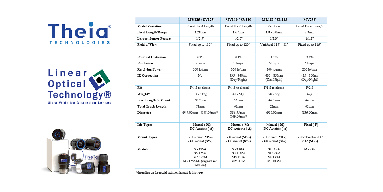
The table below shows a complete look at the specifications of Theia’s ultra-wide, no-distortion lenses including the model variations and models in production:
| MY125 / SY125 | MY110 / SY110 | ML183 / SL183 | MY23F | |
|---|---|---|---|---|
| Model Variation | Fixed Focal Length | Fixed Focal Length | Varifocal | Fixed Focal Length |
| Focal Length / Range | 1.28mm | 1.67mm | 1.8 - 3.0mm | 2.3mm |
| Largest Sensor Format | 1/2.5" | 1/2.5" | 1/2.3" | 1/1.8" |
| Field of View | Fixed up to 135° | Fixed up to 120° | Varifocal 115° - 88° | Fixed up to 116° |
| Residual Distortion | < 3% | < 1% | < 1% | < 1% |
| Resolution | 5+mpx | 3+mpx | 5+mpx | 5+mpx |
| Resolving Power | 200 lp/mm | 160 lp/mm | 200 lp/mm | 200 lp/mm |
| IR Correction | No | 435 - 940nm (Day/Night) | 435 - 940nm (Day/Night) | 435 - 940nm (Day/Night) |
| F/# | F/1.8 to closed | F/1.8 to closed | F/1.8 to closed | F/2.2 |
| Weight* | 83 - 117g | 47 - 51g | 58 - 66g | 62g |
| Lens Length to Mount | 58.9mm | 56mm | 44.3mm | 44mm |
| Total Track Length (TTL) | 71mm | 68mm | 62mm | 62mm |
| Diameter | Ø47.00mm - Ø48.00mm (lens envelope)* Ø24.50mm (clear envelope) |
Ø36.35mm - Ø49.00mm (lens envelope)* Ø13.60mm (clear envelope) |
Ø50.00mm (lens envelope) Ø15.60mm (clear envelope) |
Ø36.50mm (lens envelope) Ø15.60mm (clear envelope) |
| Iris Types | - Manual (-M) - DC Autoiris (-A) |
- Manual (-M) - DC Autoiris (-A) |
- Manual (-M) - DC Autoiris (-A) |
- Fixed (-F) |
| Mount Types | - C mount (MY-) - CS mount (SY-) |
- C mount (MY-) - CS mount (SY-) |
- C mount (ML-) - CS mount (SL-) |
- Combination C / M12 (MY-) |
| Models | SY125A SY125M MY125M MY125M-E (ruggedized version) |
SY110A SY110M MY110A MY110M |
SL183A SL183M ML183A ML183M |
MY23F |
8. Conclusion
Top-down, the mission sets the requirement: a gimbal lens for a Group 1 or 2 UAS must deliver a wide field of view — typically 90–135° — without sacrificing the geometric fidelity an operator or downstream algorithm depends on, all while operating within a sealed weight-constrained payload that survives the thermal and mechanical environment of flight.
Bottom-up, it's the optical and mechanical design that has to close that gap. A rectilinear, no-distortion design holds straight lines straight across that same 90–135° field of view, where a conventional wide-angle or fisheye lens would bow them, providing improved edge resolution compared to typical wide lenses with barrel distortion. An athermalized design keeps focus stable as temperature swings [20]. NIR correction extends usable performance into low-light conditions and covert missions. Documented shock/vibration testing proves the housing and optics hold up under flight loads.
Together, the physical characteristics and performance capabilities of Theia’s ultra-wide, no distortion lenses provide an excellent solution optimizing for both top down and bottom-up UAS mission critical requirements enabling them to perform reliably in a sealed, size, weight, and power constrained component of the aircraft.
//
©2026, Theia Technologies. 29765 SW Towne Center Loop W Ste 4 Wilsonville OR 97070
+1 (503) 570-3296 Fax +1 (503) 570-8637
Email: info@theiatech.com
Specifications subject to change without notice. Modification of this document is not permitted without written permission from Theia Technologies.